Monday 8 February 2016

Springboard.

The springboard and what it needs to be able to do is a bit of a mystery to me.

As the name suggests I guess it should be able to take shocks when sailing on uneven ice. The following question is how stiff should the springboard be and how do you measure the stiffness? No idea at this point! The DN ice boat does not have a springboard it uses a spring between hull and front runner chock so I guess no help can be found from DN forums.

Another thing I'm wondering about is caster angle. Is it desirable to have a caster angle on the front runner steering shaft? And if so what should the angle be?  I think applying a caster angle could make the steering more "user friendly". The Ice boats I have sailed tend to have quite aggressive steering. I plan to steer my boat with feet only, no tiller.

Third issue is the length of the springboard. How does the length of the springboard affect the handling of the boat? The longer the springboard is the easier it should be to tip the boat over.

It's been a couple of days since I originally wrote the questions above and since then I have had some time to seek information and give the issues some thought. I came up with the following conclusions.

Bernd Stymer has described building a spring board of two 12mm planks glued together so that's what I'm going to do too! What ever stiffness I end up with after gluing the planks together is what I tend to use!

I have been seeking the internet for information about caster angle for iceboats. I only found one article about caster angle or tilted pivot angle as it was called. The article  mentioned a maximum value of four (4) degrees tilted pivot angle. The reason for the maximum value was a fear of front runner body hitting the front runner chock. I don't expect this to be a problem with the front runner chock I plan to build so I decided to aim for five (5) degrees caster angle! Why five degrees? Well I had the calculations ready from when making the rear runner plank and it was close to four degrees mentioned in the article...As good as any other guess!

The length of the plank I measured from the drawing in the building instructions!

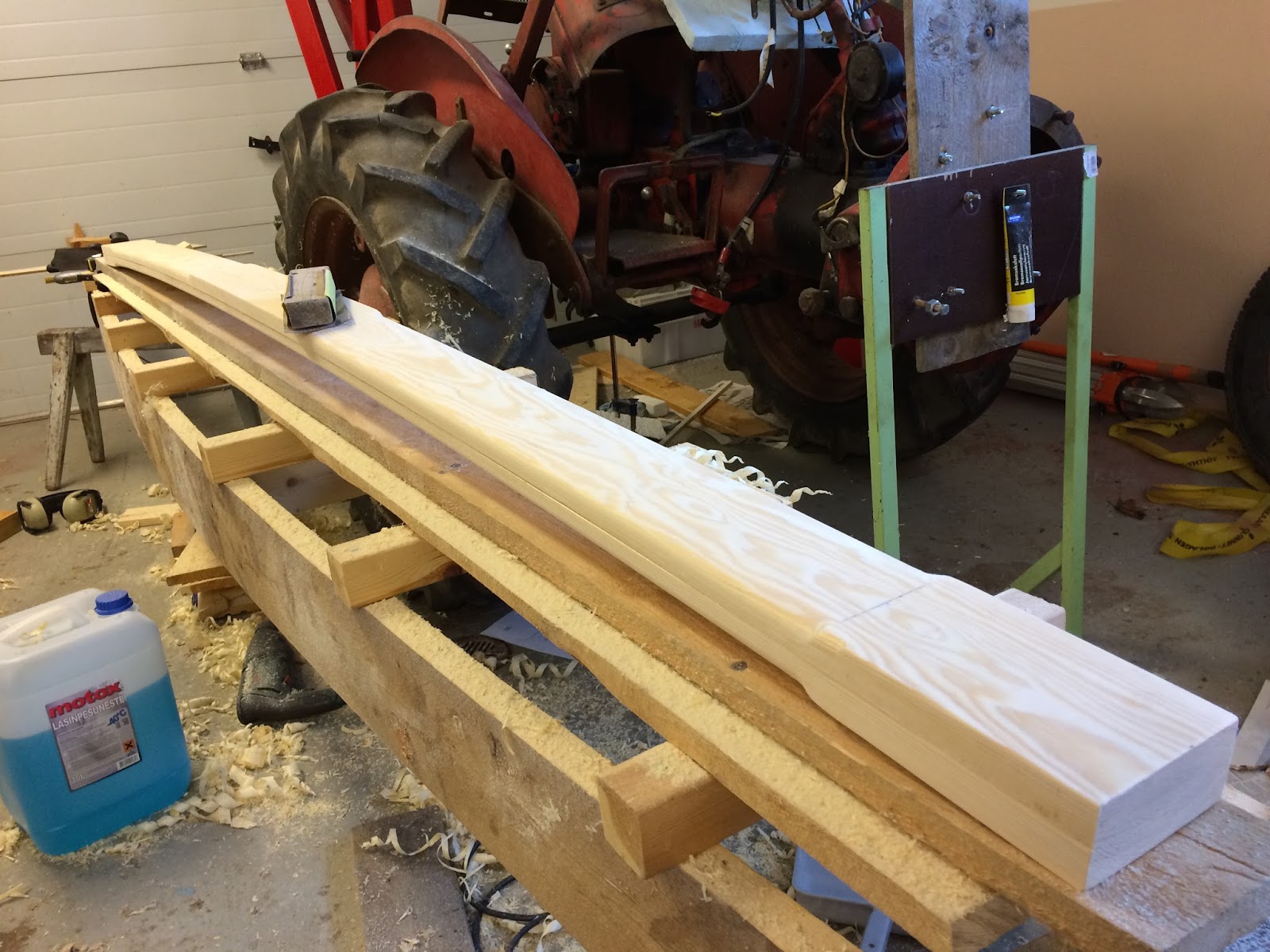
Now that I have a plan it's time to start building the springboard. I had originally bought a 120 X 15 mm plank to use for building the springboard. Since my plan is now to use 12 mm plank I first had to get some help from a friend who owns a thickness planer to get the plank thickness corrected.

Preparing to glue the boards together.


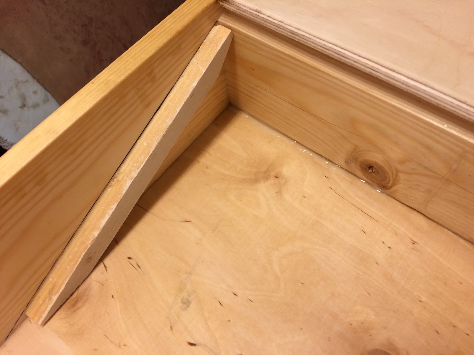
The plank is glued up side down. In the right side of the picture you can see that I have tried to prepare the five degrees caster angle already at this stage. In this way I should be able to drill the hole for the steering shaft in a straight angle towards the springboard.


Drilling the hole for the steering shaft in a straight angle towards the reinforcement piece. Once the reinforcement piece has been glued in place I will drill the last bit true the spring board by hand.


Glue clamps removed. The plank bounced back quite a lot this time witch was expected since bending radius was small causing big tension when forcing the plank down in the gluing phase.


Trying to determine what the caster angle actually landed on.


Result about four (4) degrees!


Favorite tool used for making the sides of the spring board round.


The result.


Preparing to glue the reinforcement piece.


A lot of glue clamps for a small piece of wood!


Glue clamps removed and drilling the hole true the springboard. It would have been smarter to drill the entire hole in one go when the springboard was ready!


This piece under the springboard should not be needed but because of my experiment with the caster angle the board is slightly curved were the front runner chock will touch the spring board. I'm worried this might cause problems when steering! So I glue this additional piece in hope that the front runner chock will be able to turn freely.


Once the glue has dried the springboard is ready!


Sunday 31 January 2016

Runner plank part two. Adjusting the stiffness of the plank.

 After the glue clamps were removed the plank kept its shape well, it bounced back about 5mm.


 I recall reading somewhere that for the Isabella Iceboat a good value for runner plank stiffness is when the rear runner plank bends 4-5 cm when having 100 kg on the middle of the runner plank. Most of the information available on the internet is for the DN iceboat. For the DN the stiffness is determined in relation to the sailors weight. One value I found for the DN is sailors weight +15-20 kg should cause about 50 mm bend. In  my case both of the above is roughly the same so I will try to get the plank stiffness to be in that range.

Setting up the test. After this picture was taken I also added some  round pipes to act as rollers under the piece of plywood in one end of the plank to minimize the influence of friction between the plank and floor.

.

Measuring the distance to the floor before applying weight on the plank.


About 100 kg.


The plank was too stiff so material from the plank needs to be removed to make it bend more. First I rounded the corners with a router but the impact on the stiffness was
limited. I ended up using the hand planer, removing material from the forward and aft part of the plank making the cross section shape of the plank towards oval instead of rectangular as it was originally.

 The steps with measuring and removing material was repeated until I finally ended up with the plank bending ~40 mm with 100 kg weight on it. This is still in the stiffer end of the scale but I decided not to use any more time on this phase of the build.


A finishing touch with sand paper and the rear runner plank is considered ready. In this picture it can also be seen that I have left the ends in rectangular shape this because I believe it will be easier to fasten the steel fittings to a rectangular shape. Also the upper middle part of the plank  that will touch the hull was left in rectangular shape.


Sunday 24 January 2016

Runner plank.

In the plans the rear runner plank is suggested to be made of a straight 45X95 mm  plank and to use wedges to achieve a five (5) degree toe in on the runners. This so that when sitting in the boat the runners will hit the ice in a  ninety (90) degrees angle. Building the runner plank in this way is easy and I'm sure it will work fine, therefore I will leave it as plan b in case my plank turns out to be a failure.

I am trying to make the runner plank as on a DN iceboat with a bent plank to achieve the toe in on the runners. Building the plank in this way is obviously more complicated and much more time consuming than using a straight plank and I'm not sure there are any advantages except that its more fun to build.

Preparations.
About ten years ago I built a strip kayak. I had saved the building jig and now I finally got some use for it again.


The planks sawed to correct length.


Trying out if the planks will bend enough.


Some math was needed to get the angles right.


Applying glue.


The traditional kind of glue clamp is not optimal for this job. It is difficult to get even pressure over the entire plank. But this is what I have available so this is what I try to manage with.


All clamps in place. I tried to get a straight part in the middle witch is the same width as the hull of the boat. Now I just hope the plank will keep its shape when removing the glue clamps.


Saturday 16 January 2016

Mast Foot

I made the mast foot according to the design mentioned in the plans for IsabellaClassic. The reason for choosing this design is that I haven't made up my mind how to make the short support mast that holds the windsurfing rig up. The design with 3 holes enables testing different solutions and also a possibility to trim the boat a bit by changing in witch hole the mast is.

The mast foot is made of two pieces of 90 X 21mm planks that are glued together. One of the planks has holes for the mast and support mast. Also the steering mechanism is part of the mast foot.


Preparing to glue the pieces together.


Since the pieces did not fit at all I had to find a way to force them straight when gluing them together.


Fabrication of mast foot continues. In the right side of the picture the hole for the M8 bolt that will act as shaft for the steering mechanism can be seen.


The bolt head and washer has to be lowered so that the mast foot can be glued and screwed to the deck. I used a router (seen in the picture above) to make the lowering.


Testing how the mast foot will look on the boat.


First "test drive". Safety is important when ice sailing ;-)


Almost ready for assembly just have to drill the holes for the screws. 


Mast foot was glued and screwed for maximum strength.


Tuesday 12 January 2016

The deck.

Before the deck plywood is glued on, the hull is filled with polystyrene foam board. This to ensure that the ice boat does not sink in case ending up in the water.


 I used a saw, wire brush and vacuum cleaner for shaping the polystyrene. So far this has been the only unpleasant job of the build. Even if using the vacuum cleaner the polystyrene balls get stuck every where.


Also the small box in front of the seat is filled with polystyrene.


Sometimes you have to improvise a bit...

At this point I drilled the two 8 mm holes for fastening the front runner plank.


I use a car exhaust gas pipe clamp as fastening point for the blocks that will be used for trimming the sail.


Same procedure as for gluing the bottom plywood.


After the glue has dried the hull is taken out side to plane of the excessive plywood and given a finishing touch with sand paper.


Saturday 9 January 2016

The bottom.

With the frame for the hull ready the next step is to cut the plywood sheets for bottom and deck. At this point I cut the plywood quite roughly with some mm safety margin to enable adjustment when gluing the sheets to the frame. The plywood sheet for the bottom needs to be extended since the hull is over 3,2 meters long and the plywood covers the entire bottom. The joints for the extension pieces where planned down to a big angle to maximize the surface at the joint and glued together with white water based weather resistant glue.


As the garden table was needed for working with the plywood sheets the frame was stored under the roof.


With the bottom plywood extended and roughly cut it is ready to be glued to the bottom of the boat. I  set up the job completely once before actually applying any glue to make sure I had everything needed. Again I used white water based weather resistant glue. I chose not to use any screws here. I believe the adhesive bond will be strong enough.


Wednesday 6 January 2016

Starting the build.

I have chosen an ice boat design by Bernd Stymer that he calls Isabellakiss 2012. The design should be fairly easy to build. The plans can be found and downloaded from Bernds homepage. If you are thinking of starting a Isabellakiss build I recommend to print the plans for both his designs since the plans for the Isabella classic contains a bit more details than the Isabella kiss plans. With Bernds permission I have added a link to his home page:
http://www.isabella-iceboat.com/isabella.html

After studying the plans I started the build by going to one of the local hardware stores and bought the needed material for the ice boat hull. Following material was bought:
Side planks spruce 15 X 90 mm.
Middle plank spruce 28 X 90 mm.
Runner plank spruce 20 X 90 mm (two will be glued together).
Nose plank spruce 15 X 120 mm (two will be glued together).
Birch plywood 6,5 mm for deck and bottom.
Birch plywood 9 mm for backrest.

The frame for the hull was built on our garden table that I had put in level to make sure the hull would become straight. I admit that the building platform could have been more rigid! But it worked decently. When assembling the frame I used screws and water based "white" glue suitable for outdoor use.